Medford National Forest Unit
In this example, a GFLOW model of a National Forest Unit in Northern Wisconsin is constructed, similar to the one documented in this study. The files for this example can be found in the examples/medford subfolder of the Linesink-maker repository.
Configuration file in yaml format (Medford_lines.yml)
 1GlobalSettings:
 2  # file path where intermediate and output will be generated.
 3  working_dir: '.'
 4  # ESRI projection file specifying the
 5  # projected coordinate reference system (CRS) for the model
 6  prj: shps/Medford_nf.prj
 7  # global resistance value to apply to all resistance LinesinkData
 8  # (c parameter in the GFLOW documentation)
 9  resistance: 0.3
10  # global streambed thickness value to apply to all resistance LinesinkData
11  # (delta parameter in the GFLOW documentation)
12  global_streambed_thickness: 3
13  # aquifer thickness in model units
14  # (used for calculating lambda parameter in determining resistance;
15  # see GFLOW documentation on "Dealing with Resistance to Flow into Surface Waters"
16  # https://www.haitjema.com/documents/Dealingwithresistancetoflowintosurfacewaters.pdf)
17  H: 100
18  # representative hydraulic conductivity for computing lambda
19  k: 10
20  # default (PEST) parameter name for linesink resistance
21  ScenResistance: Rlinesink
22  # model length units (feet or meters)
23  ComputationalUnits: feet
24
25ModelDomain:
26  # polygon shapefile indicating the desired model extent
27  # LinesinkData within this area but outside of the near or mid-fields
28  # will be zero resistance (specified head)
29  farfield:
30  # A distance (in GIS or Basemap units; typically meters) that defines
31  # the extent of model farfield area as a buffer distance around the nearfield polygon
32  # (can be specified in lieu of a polygon shapefile under the farfield: key)
33  farfield_buffer: 15000
34  # polygon of the model nearfield area, where LinesinkData will be given
35  # resistance and routed
36  routed_area: shps/Medford_nf.shp
37  # polygon of area of focus within routed area (optional)
38  nearfield: shps/Medford_unit.shp
39
40NHDFiles:
41  flowlines: shps/Medford_flowlines.shp
42  elevslope: shps/elevslope.dbf
43  PlusFlowVAA: shps/PlusFlowlineVAA.dbf
44  waterbodies: shps/Medford_waterbodies.shp
45
46Simplification:
47  # maximum distance a simplified line can deviate from the original linework
48  nearfield_tolerance: 100
49  # maximum distance a simplified line can deviate from the original linework
50  routed_area_tolerance: 300
51  # maximum distance a simplified line can deviate from the original linework
52  farfield_tolerance: 500
53  # minimum stream order to retain in farfield -->
54  min_farfield_order: 2
55  # minimum sized waterbodies to retain in routed area (km2)
56  min_waterbody_size: 1
57  # minimum size of waterbodies to retain in nearfield (km2)
58  min_nearfield_wb_size: 0.01
59  # minimum size of waterbodies to retain in farfield (km2)
60  min_farfield_wb_size: 1
61  # Drop ephemeral streams from routed area outside of nearfield
62  drop_intermittent: True
63
64Outputs:
65  outfile_basename: Medford
66  error_reporting: linesinkMaker_errors.txt
The GlobalSettings block
The GlobalSettings: block in the configuration file contains settings that apply to the whole model. The resistance: , global_streambed_thickness:, H: (representative aquifer thickness), and k: (representative aquifer hydraulic conductivity) are all used to compute the characteristic leakage length (\(\lambda\)) needed for estimating an appropriate width parameter for lakes (Haitjema, 2005), and are given in the model length units (ComputationalUnits:). working_dir: specifies the location where output from Linesink-maker will be written; prj: is a file path to a projection file containing a well-known text (WKT) representation of the projected CRS for the model.
The ModelDomain block
The ModelDomain: block allows specification of different areas of model refinement.
Specifying one or more nearfields
With the nearfield: key, the user can specify one or more polygon shapefiles defining the primary area of focus for the model. A single polygon shapefile containing one or more nearfield area polygons can be specified as shown above:
nearfield: shps/Medford_unit.shp
Alternatively, multiple polygon shapefiles can be specified in a list:
nearfield:
- file1.shp
- file2.shp
- ...
In both cases, Linesinks within the specified area(s) will be simplified to a global distance tolerance specified under the nearfield_tolerance: item (see below).
Alternatively, different simplification tolerances can be assigned to each nearfield shapefile as follows:
nearfield:
  file1.shp: 100  # tolerance, in model coordinate reference system units
  file2.shp: 200
  ...
Note
Specification of multiple nearfield areas requires specification of an enclosing routed_area: (see below).
Specifying an intermediate “routed area”
With the optional routed_area: key, another polygon can be supplied to define the extent of the model stream network of routed, resistance linesinks (see Haitjema, 1995). Typically, the routed area is specified at an intermediate level of detail between the refined nearfield and coarse farfield. The routed area must be a single polygon that encloses all specified nearfield areas.
Specifying a farfield
Finally, the outer extent of the model can be defined using a polygon shapefile with the farfield: key, or alternatively, as a buffer distance around the nearfield polygon with the farfield_buffer: key. The area between the nearfield polygon (or optionally, the routed area polygon) and the farfield extent is then populated with zero-resistance linesinks that form a perimeter boundary condition (see Haitjema, 1995).
The Simplification block
Source hydrography input are defined in the NHDFiles: block as shown. Currently, Linesink-maker only works with NHDPlus data. The Simplification: block controls how the hydrography input are discretized, and which features are retained. For example, a nearfield_tolerance: value of 100 meters means that the simplification of the original flowlines will be limited by the constraint that the simplified lines do not deviate from the original lines by more than this distance. With the min_farfield_order: key, lower-order streams can be excluded from the farfield linesinks (a value of 2 means that first-order streams are excluded). The min_waterbody_size:, min_nearfield_wb_size: and min_farfield_wb_size: keys control the minimimum size for the waterbodies that are included in the routed, nearfield and farfield areas of the model (in square km). Finally, with the drop_intermittent: key, streams classified as “intermittent” in NHDPlus can be excluded from the routed part of the model outside of the model nearfield. By default, all streams are included in the nearfield.
The above configuration file can be used in the following script to generate a linesink string (LSS) XML file of the stream network that can be imported into GFLOW (version 2.2 or later).
Python script to build the model (make_linesinks.py):
1import lsmaker
2
3input_file = 'Medford_lines.yml'
4ls = lsmaker.LinesinkData(input_file)
5ls.make_linesinks()
Note
The input_file path given in the above script assumes that the script is being executed in the same folder as Medford_lines.yml.
A shapefile representation of the linesinks is also produced, along with additional shapefiles of the source hydrography merged and clipped to the model area. The resulting linesinks are shown in Figure 1.
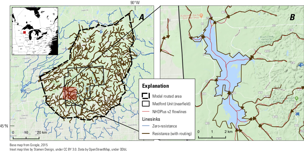
Figure 1: Linesinks produced by Linesink-maker for the Medford Unit of the Chequamegon-Nicolet National Forest. A distance tolerance between the simplified linesinks and original hydrography controls the level of detail in the stream network. Linesinks within the forest unit were created at the highlest level of detail (100 meter distance tolerance). A buffer of routed resistance linesinks disretized at a 300 meter tolerance surrounds the forest unit, to allow for accurate simulation of hydraulic divides between competing sinks and stream (base) flows into the forest unit. Coarsely discretized (500 meter tolerance) zero-resistance linesinks create a perimeter boundary condition for the solution. B illustrates the conversion of flowlines (red) into a drainage lake represented by routed resistance linesinks around its perimeter. Linesink-maker makes small adjustments to the end elevations of drainage lake tributaries to ensure proper routing in the GFLOW GUI.
Alternative XML format for configuration file (Medford_lines.xml)
  1<linesinkInput>
  2<!--
  3Notes on linesinkMaker input:
  4    Put in paths to input/output files as-is (i.e. no double \)
  5-->
  6<GlobalSettings>
  7    <!-- working_dir:
  8    file path where intermediate and output will be generated. -->
  9    <working_dir></working_dir>
 10    <!-- prj:
 11    ESRI projection file specifying the
 12    projected coordinate reference system (CRS) for the model -->
 13    <prj>shps/Medford_nf.prj</prj>
 14    <!-- preprocess:
 15    Whether or not preprocessing is needed (requires arcpy) -->
 16    <preprocess>False</preprocess>
 17    <!-- zmult:
 18    elevation units multiplier (from NHDPlus cm to model units) -->
 19    <zmult>0.03280839895013123</zmult>
 20    <!-- resistance:
 21    global resistance value to apply to all resistance LinesinkData (c in GFLOW documentation) -->
 22    <resistance>0.3</resistance>
 23    <!-- H:
 24    aquifer thickness in model units -->
 25    <H>100</H>
 26    <!-- k:
 27    Hydraulic conductivity in model units -->
 28    <k>10</k>
 29    <!-- ScenResistance:
 30    name for global resistance parameter to assign to LinesinkData-->
 31    <!-- global_streambed_thickness:
 32    Streambed thickness depth value to assign to all LinesinkData-->
 33    <global_streambed_thickness>3</global_streambed_thickness>
 34    <ScenResistance>Rlinesink</ScenResistance>
 35    <!-- ComputationalUnits: ('Feet' or 'Meters')
 36    model units-->
 37    <ComputationalUnits>Feet</ComputationalUnits>
 38
 39</GlobalSettings>
 40
 41<modelDomain>
 42    <!-- farfield:
 43    polygon shapefile (a ring, with nearfield making up the side) of the desired model farfield area
 44    LinesinkData within this area will be zero resistance (specified head) -->
 45    <farfield></farfield>
 46    <!-- farfield_buffer: numeric, default is 10,0000
 47    A distance (in GIS units) that defines the extent of model farfield area as a
 48    buffer distance around the nearfield polygon
 49    (can be specified in lieu of a polygon shapefile under <farfield>)
 50     -->
 51    <farfield_buffer>15000</farfield_buffer>
 52    <!-- routed_area:
 53    polygon of the model nearfield area, where LinesinkData will be given resistance and routed -->
 54    <routed_area>shps/Medford_nf.shp</routed_area>
 55    <!-- nearfield:
 56    polygon of area of focus within routed area (optional) -->
 57    <nearfield>shps/Medford_unit.shp</nearfield>
 58</modelDomain>
 59<!-- NHDfiles:
 60input .shp and .dbf files from NHDPlus. To include multiple files
 61(e.g. multiple flowlines files spanning multiple drainage areas)
 62simply add additional entries with same XML keyword.
 63LinesinkMakr will open all of the files and combine them.-->
 64<NHDfiles>
 65    <flowlines>shps/Medford_flowlines.shp</flowlines>
 66    <elevslope>shps/elevslope.dbf</elevslope>
 67    <PlusFlowVAA>shps/PlusFlowlineVAA.dbf</PlusFlowVAA>
 68    <waterbodies>shps/Medford_waterbodies.shp</waterbodies>
 69</NHDfiles>
 70
 71<Simplification>
 72    <!-- nearfield_tolerance:
 73    maximum distance a simplified line can deviate from the original linework -->
 74    <nearfield_tolerance>100</nearfield_tolerance>
 75    <!-- routed_area_tolerance:
 76    maximum distance a simplified line can deviate from the original linework -->
 77    <routed_area_tolerance>300</routed_area_tolerance>
 78    <!-- farfield_tolerance:
 79    maximum distance a simplified line can deviate from the original linework -->
 80    <farfield_tolerance>500</farfield_tolerance>
 81    <!-- min_farfield_order:
 82    minimum stream order to retain in farfield -->
 83    <min_farfield_order>2</min_farfield_order>
 84    <!-- min_waterbody_size:
 85    minimum sized waterbodies to retain in routed area (km2) -->
 86    <min_waterbody_size>1</min_waterbody_size>
 87    <!-- min_nearfield_waterbody_size:
 88    minimum size of waterbodies to retain in nearfield (km2) -->
 89    <min_nearfield_waterbody_size>.01</min_nearfield_waterbody_size>
 90    <!-- min_farfield_waterbody_size:
 91    minimum size of waterbodies to retain in farfield (km2) -->
 92    <min_farfield_waterbody_size>1</min_farfield_waterbody_size>
 93    <!-- drop_intermittent:
 94    Drop ephemeral streams from routed area outside of nearfield -->
 95    <drop_intermittent>True</drop_intermittent>
 96</Simplification>
 97
 98<outputs>
 99    <outfile_basename>Medford</outfile_basename>
100    <error_reporting>linesinkMaker_errors.txt</error_reporting>
101</outputs>
102</linesinkInput>